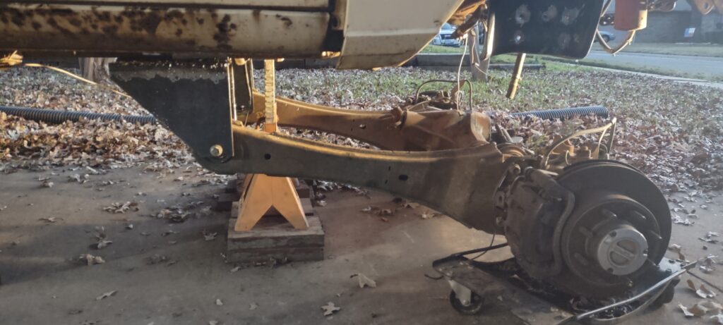
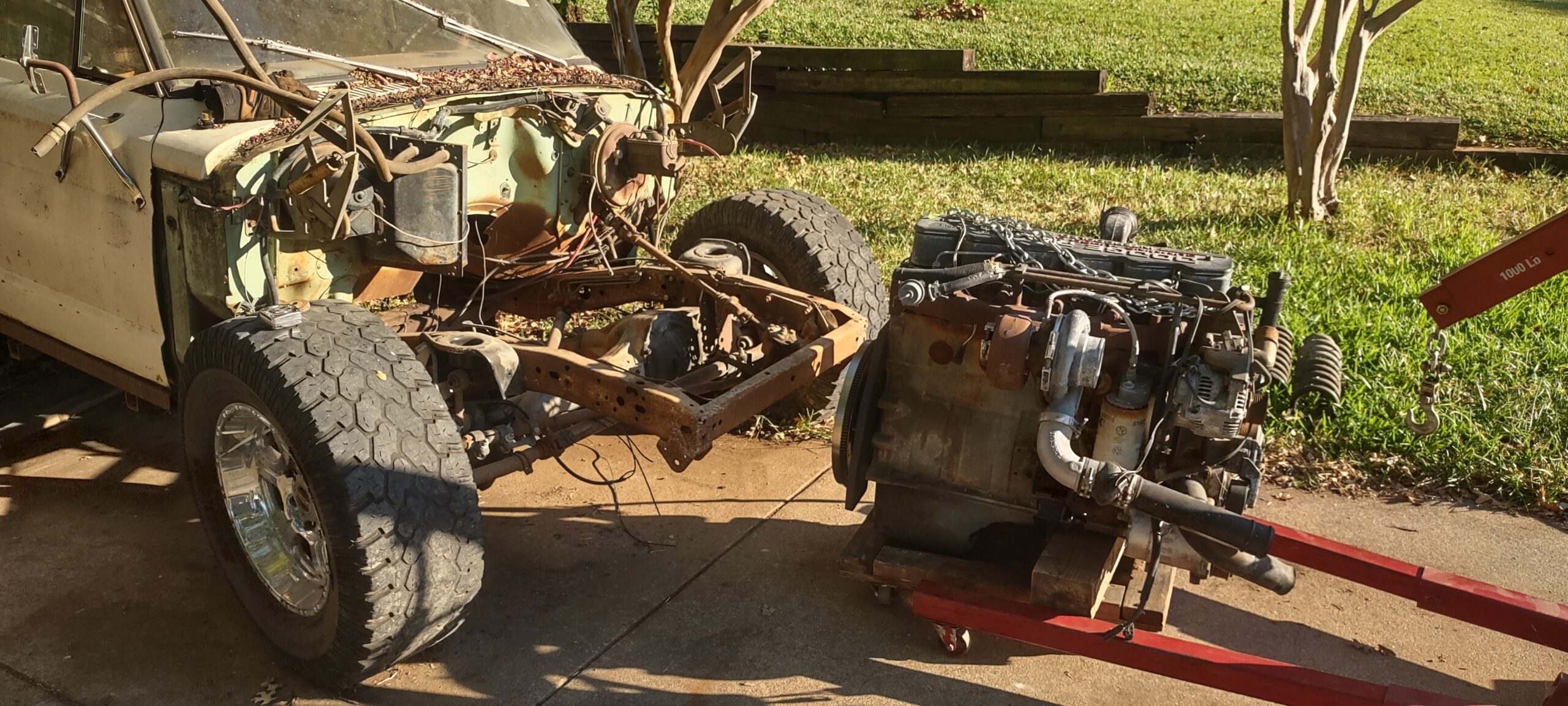
The new axle is a Dana 60 from a 2008 Ford F250. I originally purchased a Dana 60 from a 2004 (?) F250 that was on leaf springs but I couldn’t wrap my head around the suspension geometry when the leaf spring is the control arm as well. The Jeep winds up having asymmetrical leaf springs in the front where they are longer towards the rear and rather stubby in the front. I ran through all sorts of leaf spring options and couldn’t find something that I think would work, and I am never in the mood to buy and try things until I find one that works. I decided to sell what I had and switch to the coil spring version of the Dana 60. Along with the axle I picked up the steering rod, track bar, radius arms, and tried to get the coil spring buckets and radius arm brackets. The parts yard started getting shifty when it came to the brackets but I was lucky enough to get at least the coil spring buckets. The buckets are important because I am going to do the same thing I did on the rear and mount the suspension similar to the F250.
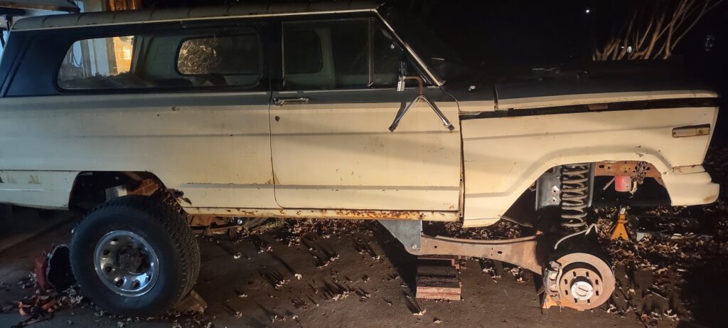
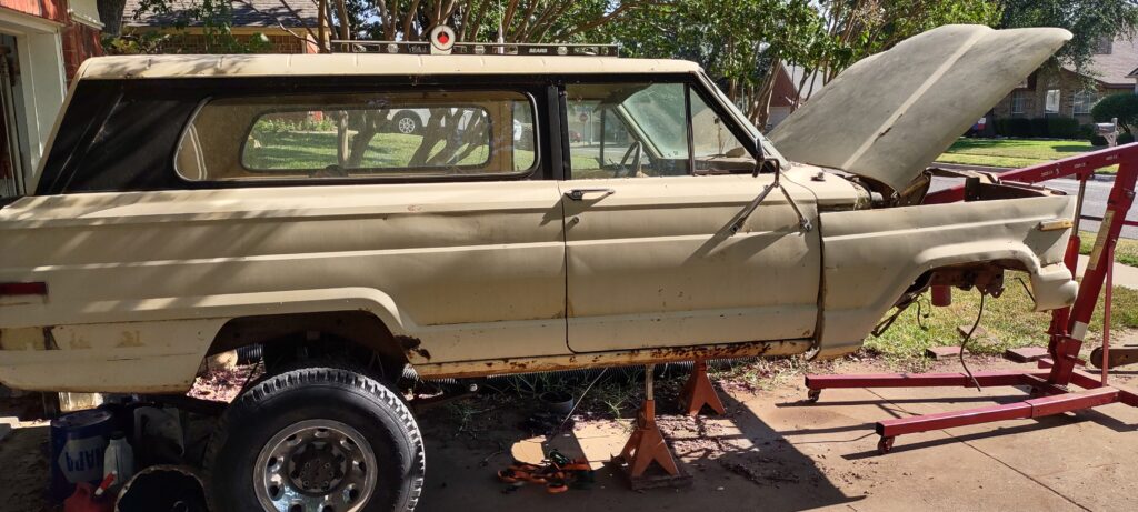
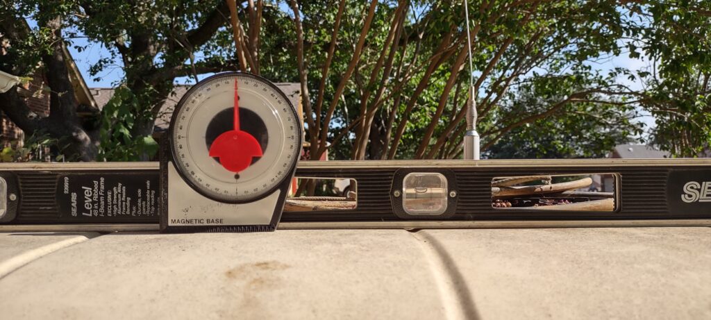
The first step I took was setting the proper ride height. I was not going for any specific height. Instead, it will be whatever height levels off the vehicle. I dropped the front suspension and leveled the truck. Yes I used a bubble level and two different types of angle finders. It’s fine, this isn’t rocket science. Just make sure the datum plane (the driveway in this case) is referenced and accounted for.
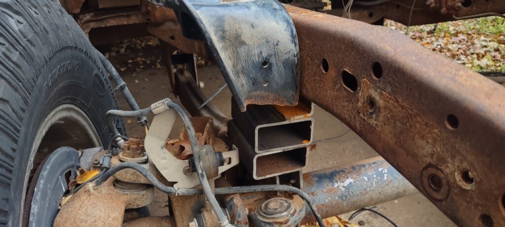
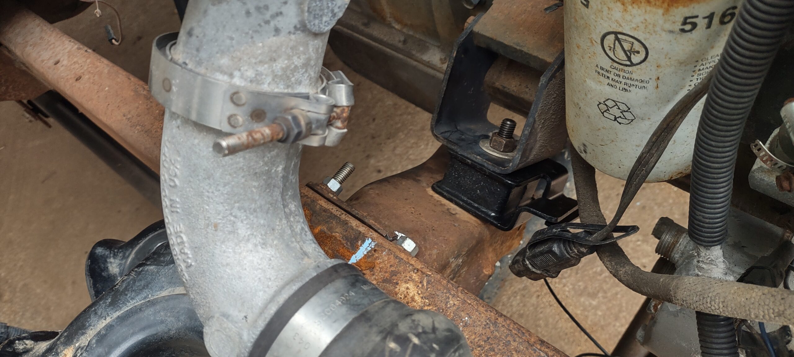
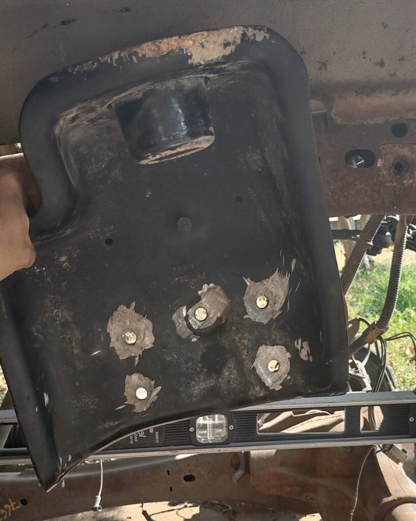
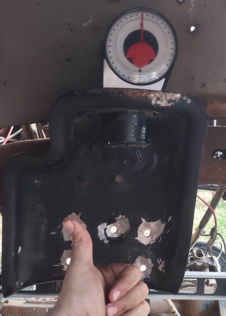
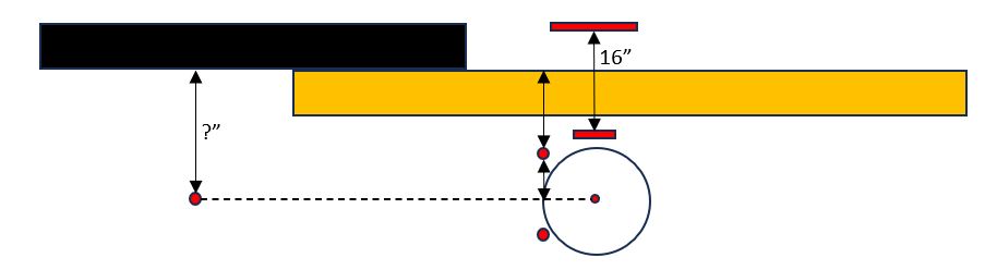
With the truck sitting level on jacks I rolled the new axle under to center the wheel in the fender. This is going to help locate the coil spring bucket. I wanted to avoid drilling more holes after having bad memories of the drilling for the rear suspension, and also didn’t want to add tubes to those holes since the frame is boxed in. Instead I utilized the existing holes where the old strut mounts went. Then I can use the old strut towers as templates to drill holes into the coil buckets. Before I can do that though I needed to determine how high or low to mount the coil bucket on the frame. This will determine ride height in the front. I need to account for the tire height and mimic what is used in the rear as well as the compressed coil spring height. Using the weight split from the Weight Calculations post, along with the spring rates, I calculated the compressed spring height to be roughly 16 inches, compressed from 20.25 inches. The coil seats in the bucket, and also on a pad on the axle. That pad height is offset from the wheel centerline. By using the wheel height, pad offset, and compressed spring height, I can determine the location height of the coil bucket. One last alignment needs to be made. To tilt the bucket or not? I pondered this for a while, as the axle rotates in an arc. If the coil springs are long enough they could bow outward under compression, so do I angle the buckets in line with the arc or keep them in line while the springs are at rest? I decided to keep the buckets in line with the coils. The only thing left is the width of the coil spring pads on the axle and if they where I mounted the buckets on the frame. They are not perfectly in line. They stick outboard but there isn’t much I can do unless I shim out the buckets or make them from scratch. Being a coil it can handle some misalignment and flex to a certain extent.
![]()
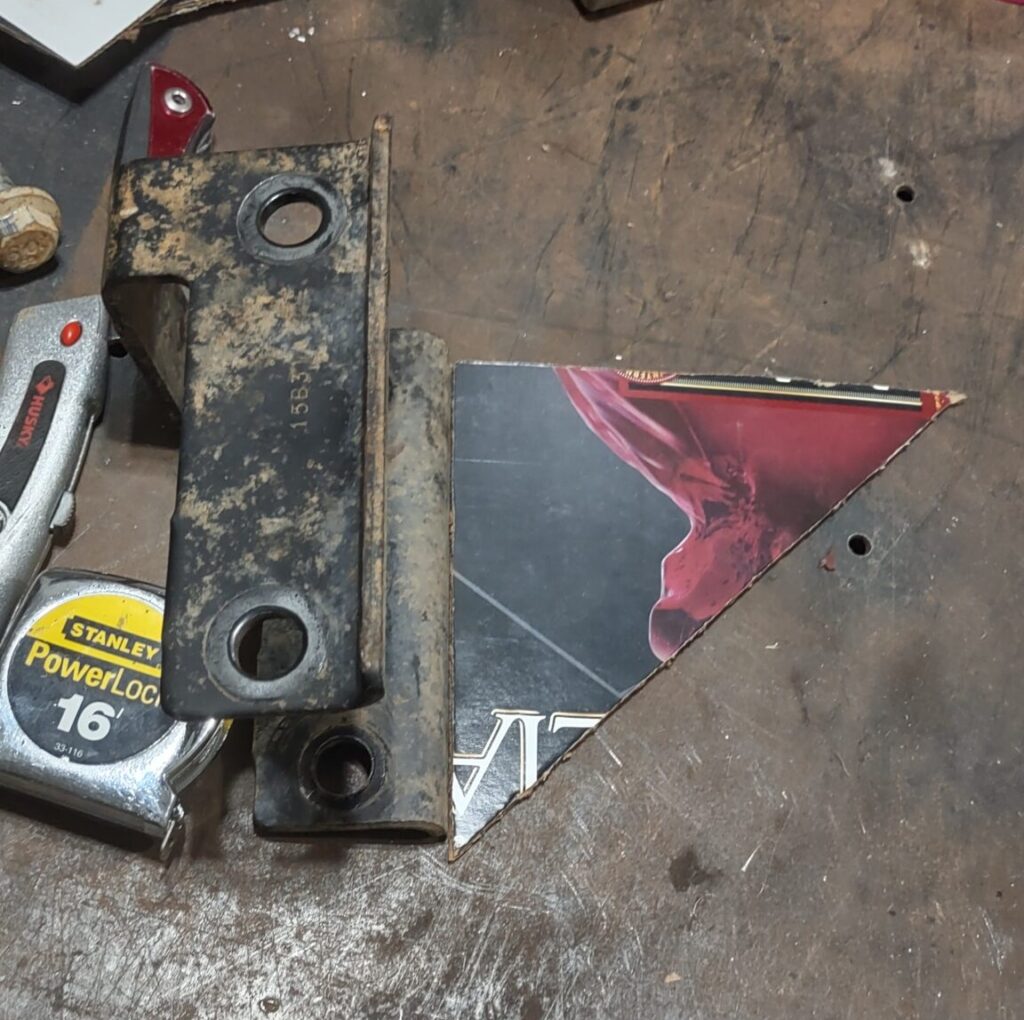
This was the relatively easy part. The next step was to create the brackets that the scrap yard didn’t get me. Hindsight, it wouldn’t have mattered because you have to alter them. The bracket sets the pivot point for the radius arm. The height of that pivot point will determine the angle of the radius arm, and the angle of the radius arm will determine the caster of the axle. As you lift the vehicle, the pivot point lifts with the frame of the vehicle, thus angling the radius arm downward towards the axle. This will in turn rotate the axle and give negative caster causing the vehicle to wonder and generally be unstable (however it will lighten the steering). To correct the caster you have to lower the pivot point of the radius arm. My target was to get the radius arm level – that seemed to be where it is supposed to be stock. To determine this location I used the bottom of the frame as my datum line. I extended that line using a level. I then put the axle in its theoretical resting spot when the spring is compressed – again, I don’t have total weight on the vehicle yet so I have to estimate. The radius arm looks like a dog bone with two mounting points on the axle so I find the height of one of those points relative to the pivot point on the other end, and then I find the height of the mounting point to the level. I can then determine the distance from the frame to the pivot point.
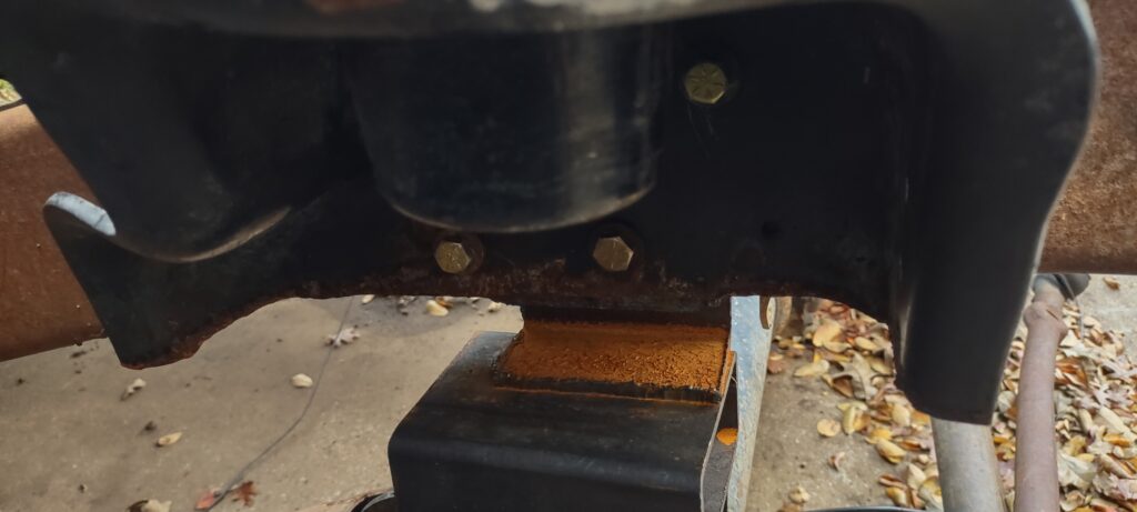
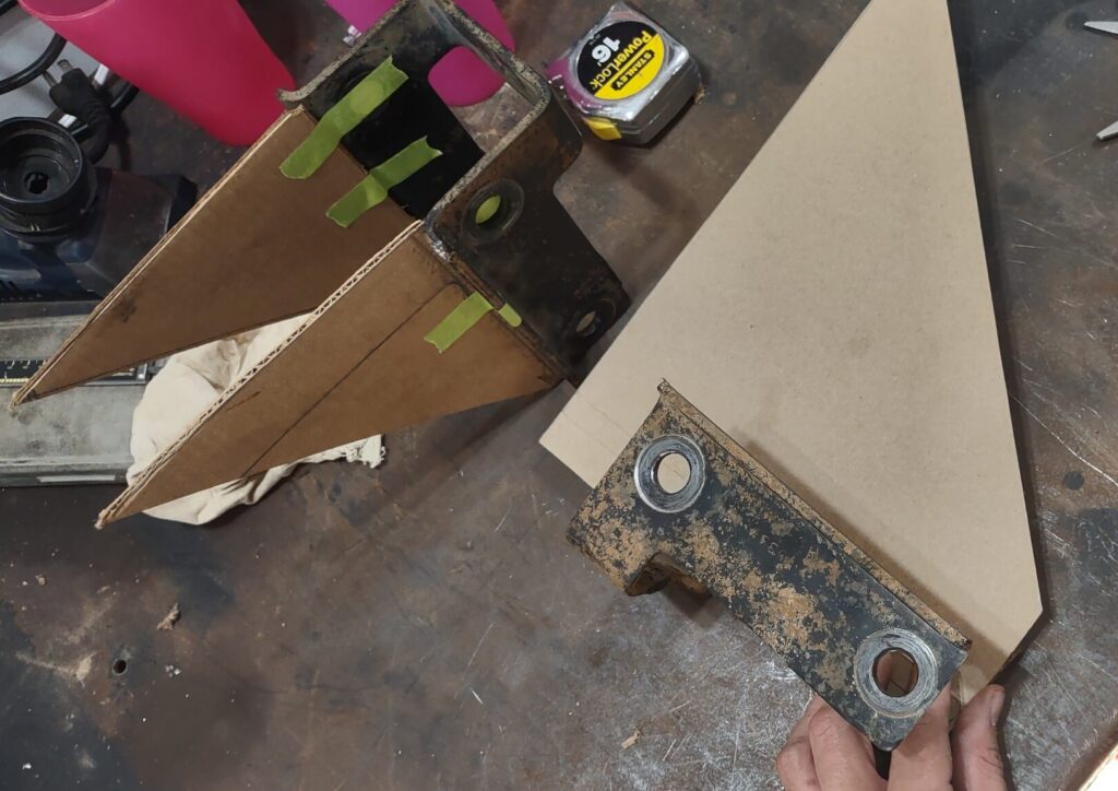
I calculated the height to be roughly 9 inches (working from memory at this point). The bracket needs to be deep enough to allow the arm to articulate. I used some cardboard to mock up what I was looking for and for added rigidity I made the bracket like a truss. I used a sheet of 3/16″ steel for these brackets, and a plasma welder with a 2×4 to cut straight lines. The original idea was to use an old leaf spring hanger to extend into a bracket but after having mocked up up the cardboard it seemed like a silly idea considering I had the material to do a full bracket.
![]()
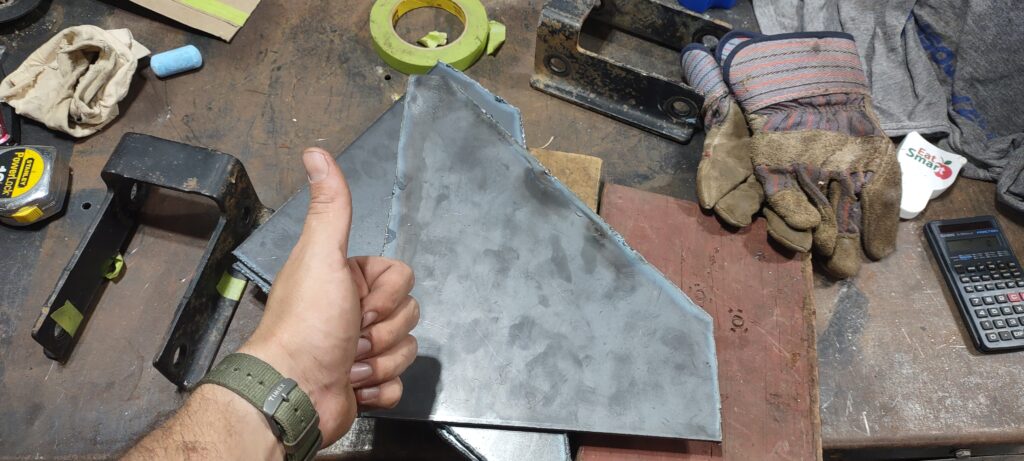
This brought me to the welding part which I am terrible at. I have a MIG welder and I could never master heat, wire speed, gas. After welding everything up, horribly, I started doing some research and wanted to try using flux core wire. No need for gas. After putting that into the machine I ran some practice beads and visually they looked ten times better. Unfortunately, I had already welded my brackets, a lot. I was not going to grind out those welds to do it again. You live and you learn. I wish I had more photos, not sure why I don’t, but at the top I added angle iron so I could cradle the frame. I ran a bead on the bottom and on the side. Originally I wanted everything to be modular and bolt on but just like the coil buckets, the frame is boxed in and I didn’t want to add tubes. The bolts would likely interfere with the transmission crossmember too. The last thing to calculate is how wide to mount the brackets on the frame. The radius arms were almost the same width as the frame and stuck out maybe 1/4 to 1/2″ outboard on either side. I was very pleased with the final product. The nose of the truck sits a little high but the springs haven’t compressed yet. If anything it may sit a little lower and at that point I can add rubber isolators to the end of the coils to lift the truck back up by an inch or so. Lastly, the coil spring buckets have significant overhang from the frame so I cut off the excess. I will address the track bar and steering rod in a later post.