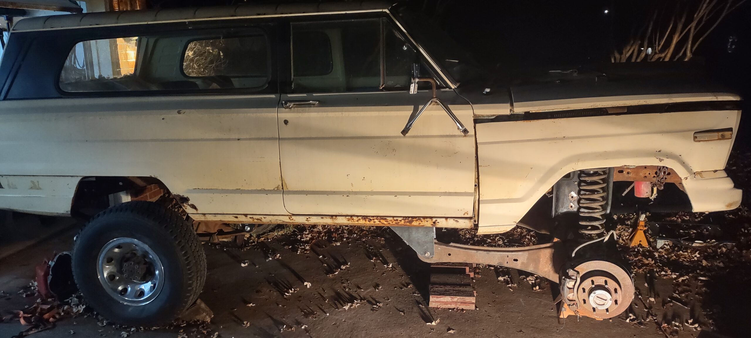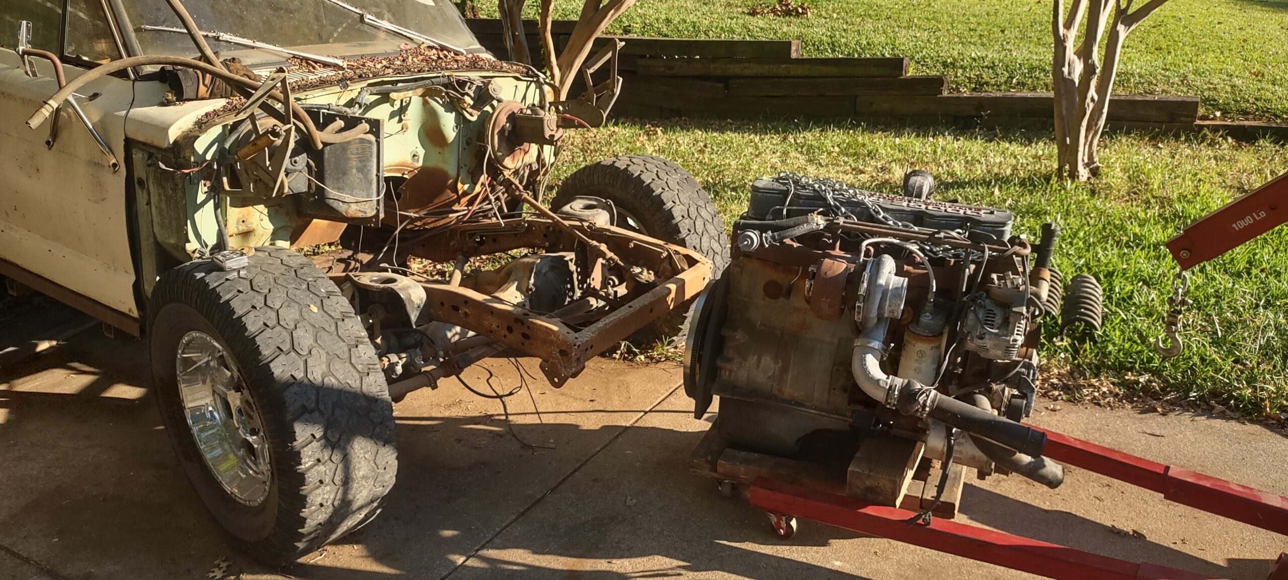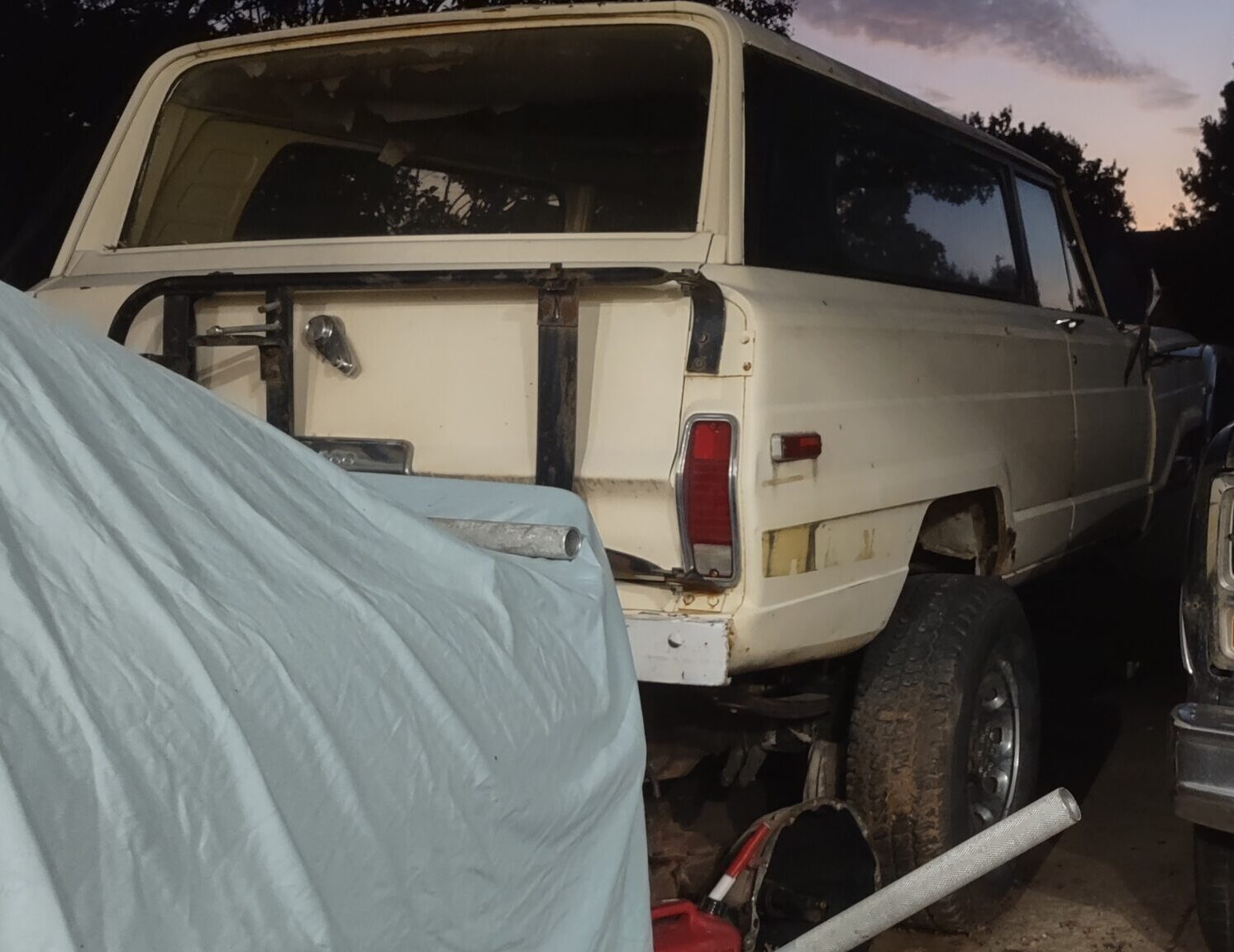
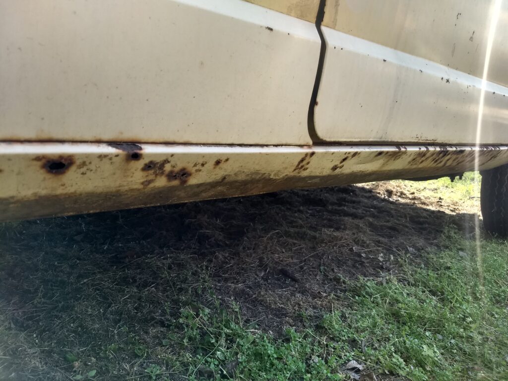
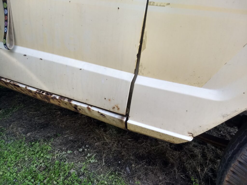
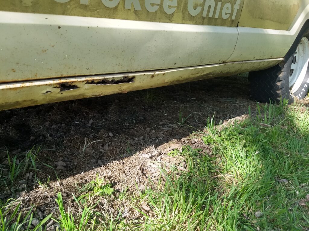
Alright, I admit, I got this idea from some examples I saw online. The rockers are rusted out and its obvious Bondo was slathered on to pretend it doesn’t exist. This is a truck, I plan on using it like a truck, which means I am not trying to make the body perfect on this. For one, I don’t think I can do body work well enough to look good, but also it’s just going to get dinged up. I cut the out the entire rocker which to my surprise had pounds of Bondo. I haven’t done much cutting of body panels on any car but my God, I’d never seen so many overlapped pieces of sheet metal. I don’t know if it is uniquely a Jeep thing however suffice to say, I’m not surprised rust formed in this cavity. Water gets in, can’t dry off, sits between the folds.
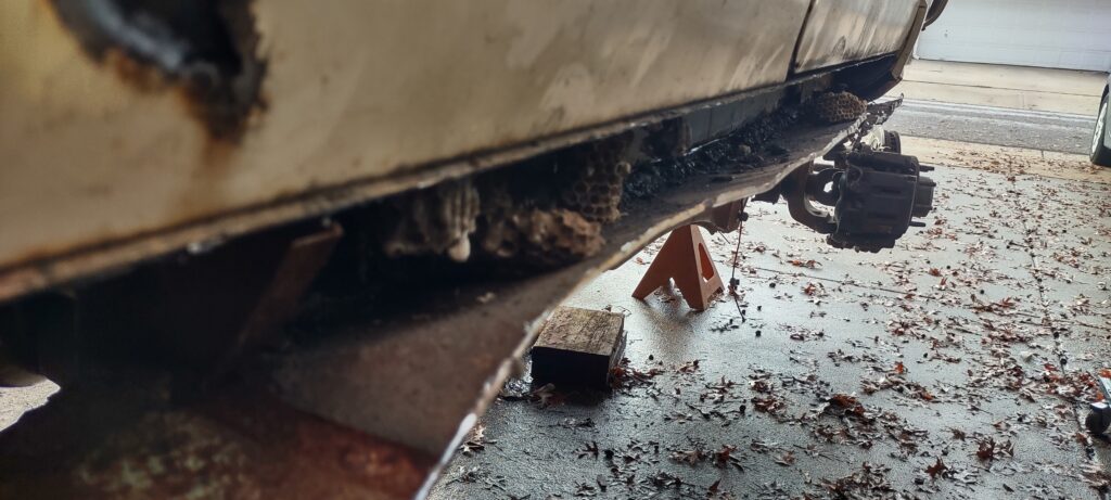
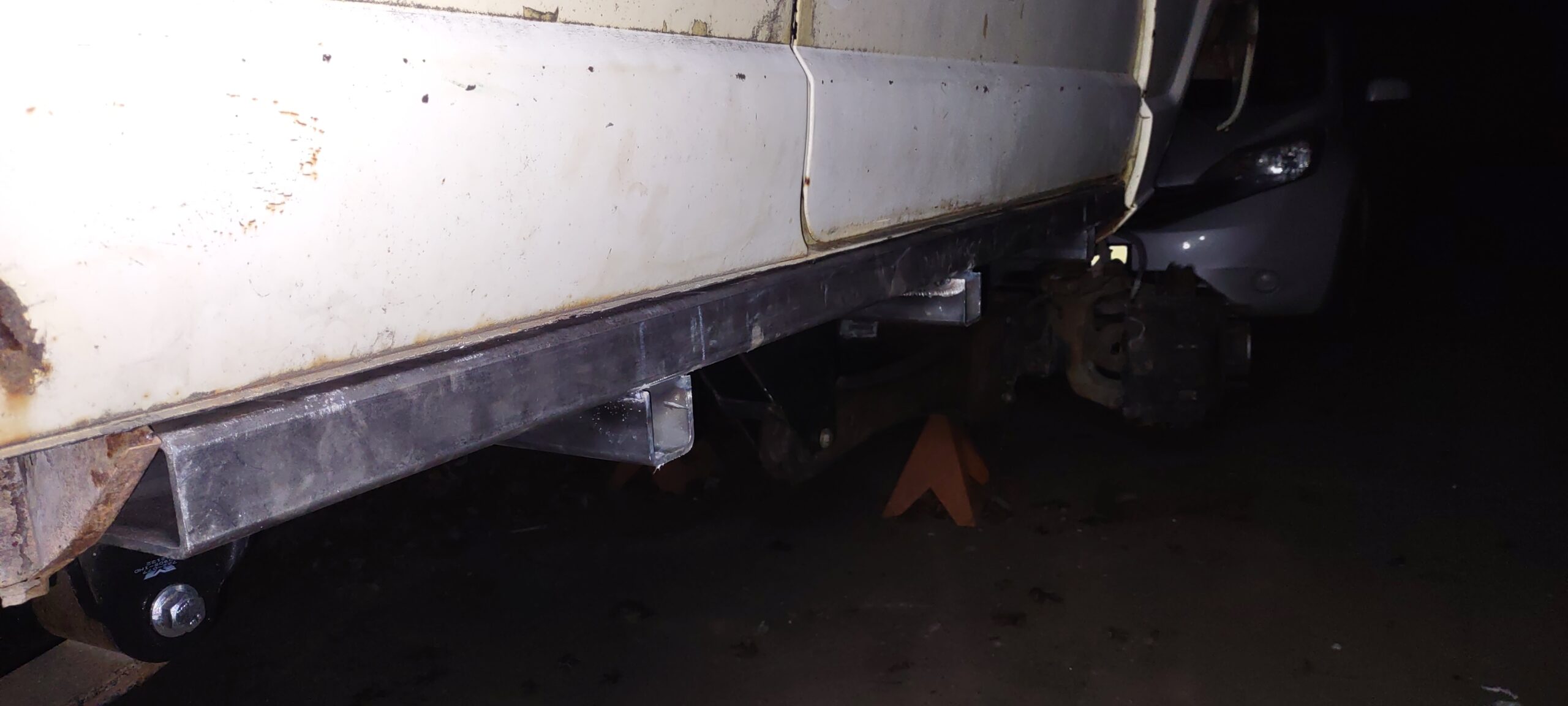
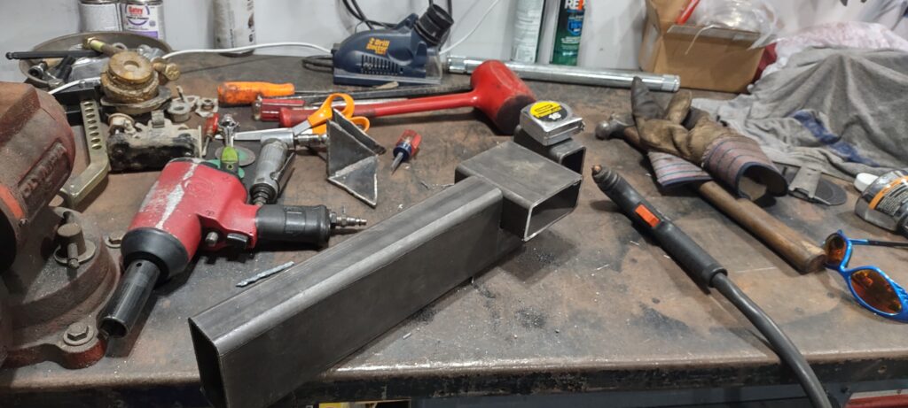
Once the rockers were removed I measured the length and set out for some 2 x 4 – 3/16″ rectangular tubing. I already had leftover 3/16″ plate on hand for the mounts. The idea is that by laying the tubing flat where the rocker once was, it neatly fills the space. The rockers will tie into the frame and act as frame extensions where they will get their strength as rock sliders (implying I would ever use them for that), and also solid jack points.
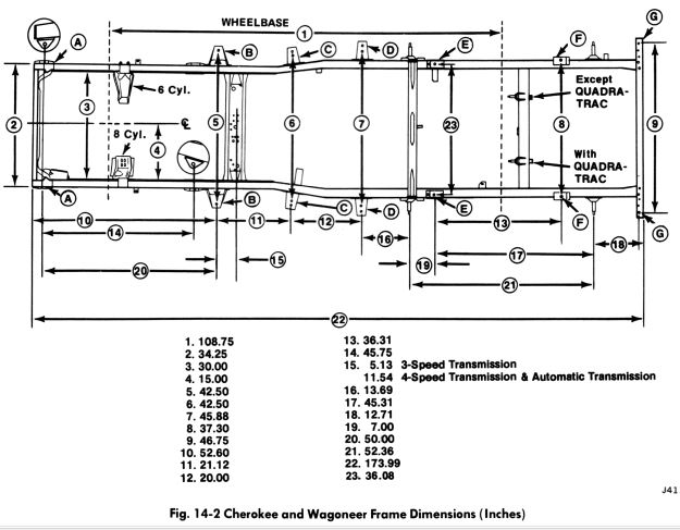
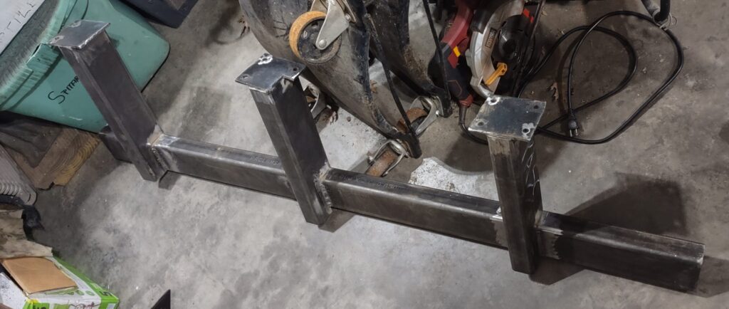
It’s important to note that the frame widens as you go towards the rear. The ‘stringers’ that will tie the rock slider into the frame will need to vary in length. The stringers will also be mounted vertically (in respect to the rectangular cross section) for more vertical rigidity. Extremely important to note, do not mount the sliders so high that they collide with the body. The body mounts on this Jeep are probably sagging so if anything it is sitting lower than what it will when they are replaced. If you were to do this with the body off then you need to be extremely careful so that the body can go back on. I used a scrap piece of 3/16″ plate to space the slider off the body when mocking up.
With the stringers running vertically, I decided to notch them for the slider to sit in. I didn’t want to weld perpendicularly onto the slider. Also, while the stringers need to be different lengths to match the frame, the ends will need to be cut at an angle so they can sit flush on the frame.
![]()
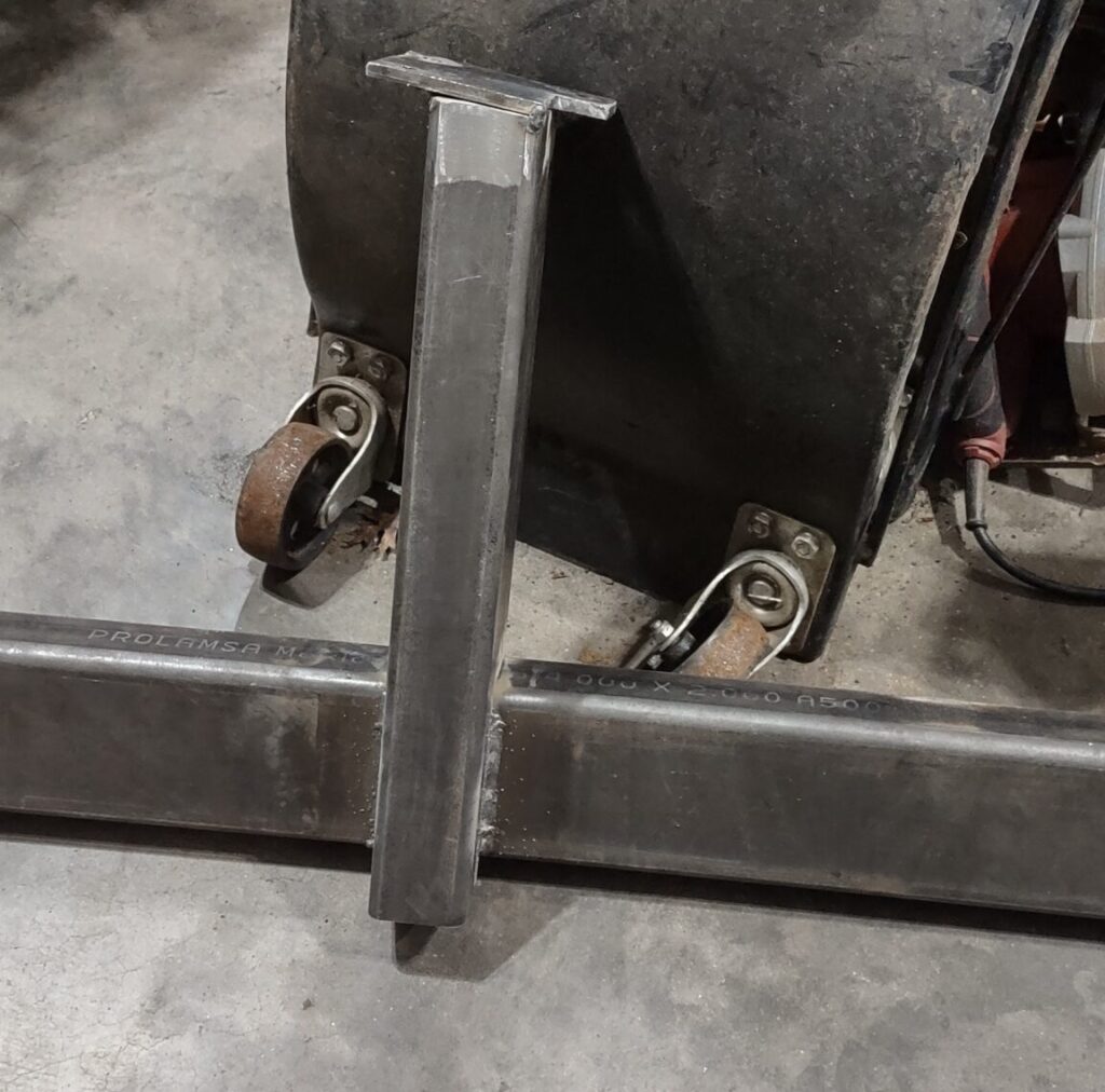
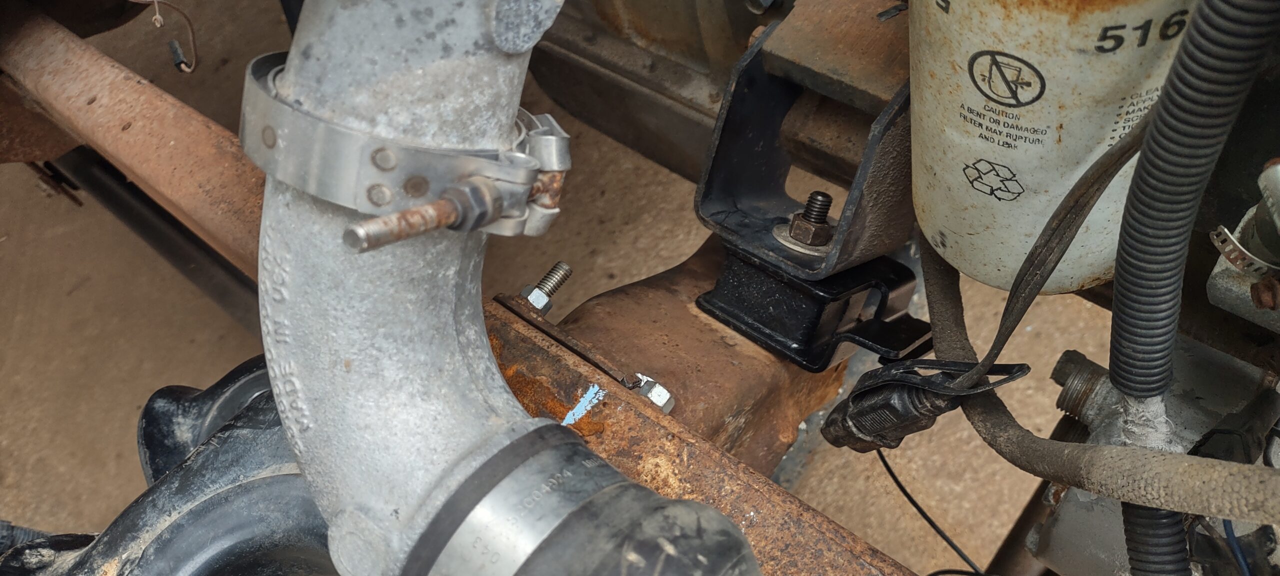
You will note the frame side mounting plates have holes drilled in them. As with the rest of the project, I wanted these to be modular so I could unbolt them however I frankly couldn’t be convinced to drill 20+ holes. Some areas where bolts would go are boxed in frame and I didn’t want to weld in tubes to support the box, and there are things on the other side of the frame in the front like a transmission crossmember which will likely move… somewhere undetermined at this point, with the new engine and transmission. It was better to just weld it and tell myself it is the frame now. I have a MIG welder which I am horrible with and found much better luck after switching it to flux core wire. If only I had done that earlier for some of the other welding on this project.
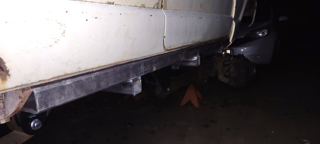
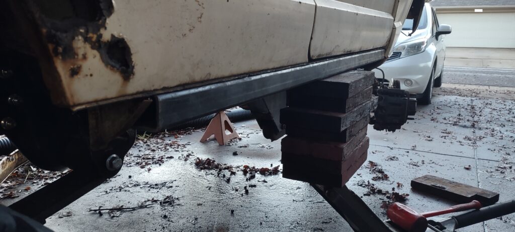
I’m pleased with the results. I load tested it with a Hi-Lift jack and it supports the weight easily. Interestingly the passenger side flexes slightly while the driver side is rigid. They were made the same way and I know it’s not the slider flexing. My best guess is a little bit of twist in the frame. The stringers being vertical I think greatly help in reducing flex however come at the cost of being 2″ below the slider… thus not making a slider because a rock will get hung up on it. Let’s not forget though, I don’t actually plan on using rock sliding. My only regret is not pushing the sliders out by a half inch. I was so set on making them flush, and they are, but the Hi-Lift jack likes to fully hook onto the slider (Hi-Lift has a ~4″ jack point which matches the 4″ slider). When jacking, it wants to pull itself into the side of the body.