It has been a while since I have touched the projects… The lack of a real plan for the next milestone has left me fumbling the ball, and the heat has provided an excuse to not get out there. Some realities of life have gotten in the way, busy with household projects, etc. Now that we are in the middle of August with hopefully the heat making a break for the rest of the year I need to make a plan so I can focus my thoughts.
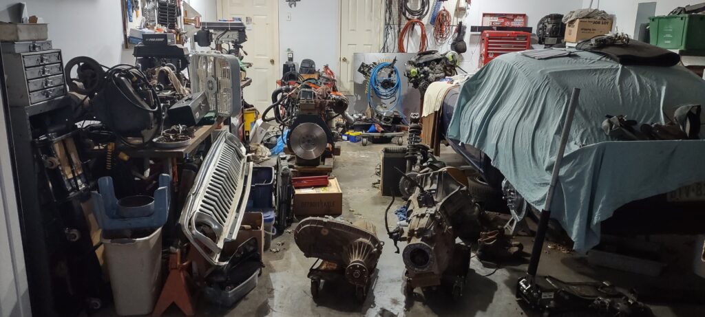
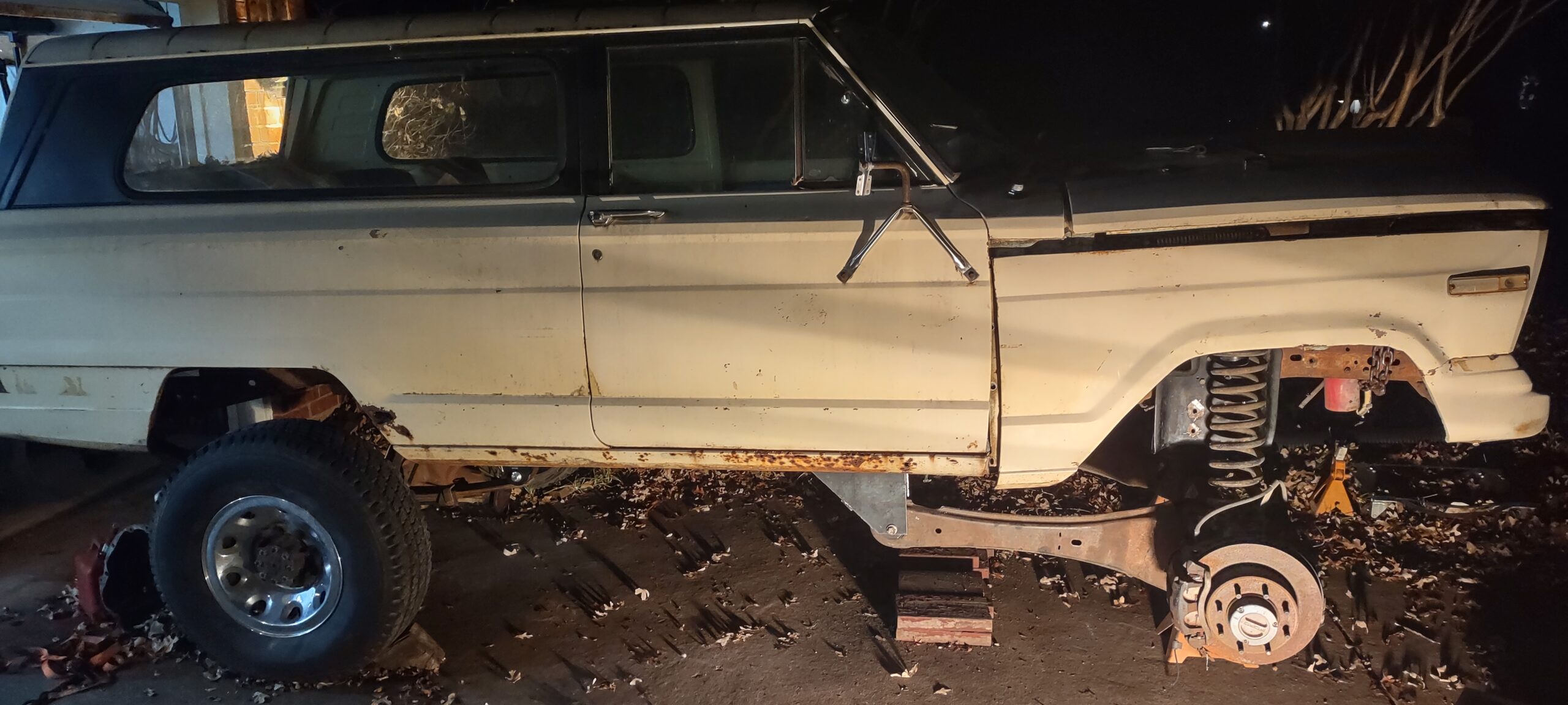
Here is where we are at. I don’t want to further myself on the 240Z project until I can clear adequate working space in the garage. I can’t clear adequate working space in the garage until I can get the engine, transmission, and transfer case in the Jeep. Just like with the suspension (I will be making a post on that shortly) there needs to be a specific order of operations so I don’t corner myself into a situation. After I roughly completed the suspension I started digging into cutting out rusty floors which was slightly intimidating and there were other factors I need to incorporate before I weld in fresh metal. For instance I need to know how big the transmission tunnel needs to be. Putting in a 6 speed transmission, it might require more space than a 5 speed (ZF5) which others have done without modification.
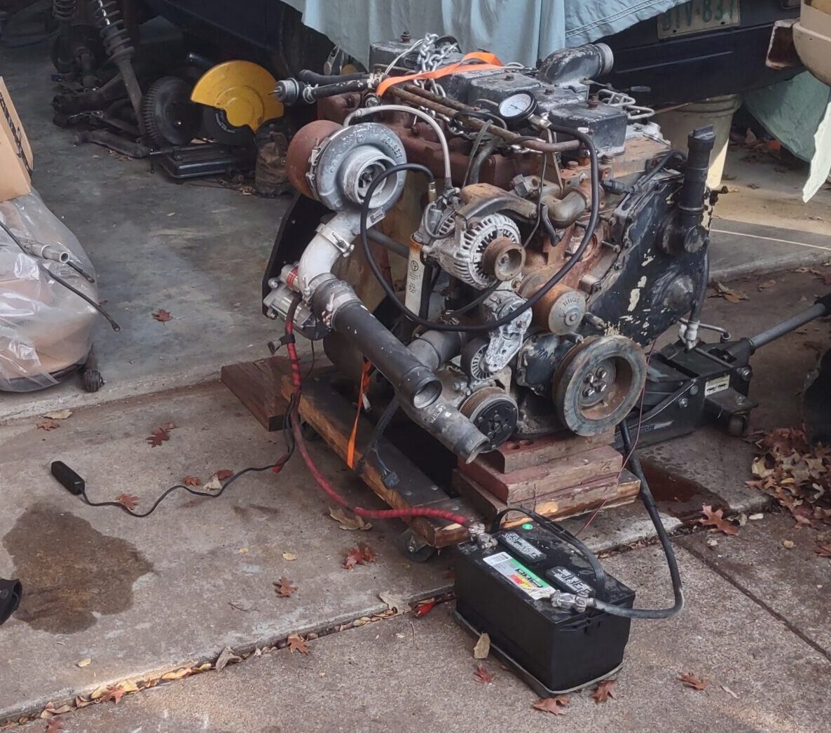
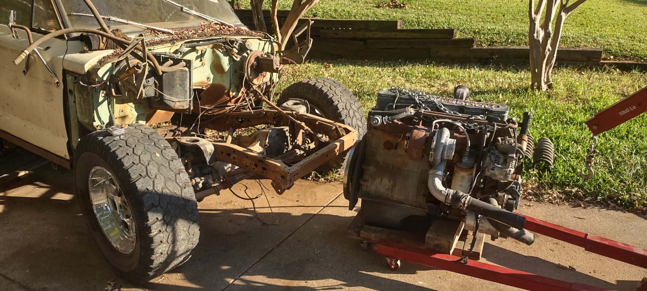
So lets get to the point. The engine, transmission, and transfer case need to go into the truck. I have replaced the seals on the seals on the engine, installed the killer dowel pin fix, and flywheel. I am envisioning the engine, transmission, and transfer case going in as an assembly. That will constitute what I estimate to be ~1600lbs. I do not want to put the engine in and then wrestle a transmission in from underneath, trying to align the input shaft splines. Usually with the smaller cars I wouldn’t mind doing this but with nearly 300lbs I am not comfortable with that.
Before it goes in:
- Install clutch
- Buy and install starter (6.7L Ford Powerstroke, need to find the year)
- Maybe test run the engine on the ground?
- Install transmission
- Install transfer case
To put the assembly in:
- Put the Jeep on dollies and flip it around. I need the front facing the garage because again, the assembly is heavy. I don’t want to wheel it out if I can help it
- Bring the engine hoist to the other side of the garage and have room to assemble it facing outward. This is where you don’t want to block yourself in. It is a game of Tetris right now
- Take the entire front clip of the Jeep off so it’s bare frame. This is easy, it’s just resting on the front right now. I want to limit how high I need to lift the assembly so we don’t make a precarious situation
- Lift and stab the assembly straight in
- While suspended I need to take the motor mounts that I have, from a 1st Gen Dodge (W-series, not D-series) and measure/eyeball where they will land on the frame
- Mark and… here is the big question, weld? More on that below
- Slide everything back out and attach mounts
- Put it all in where hopefully it rests forever
This will open up the garage significantly. A few factors to consider. Being a large inline 6, it is very long. The installs I have seen put the engine about an inch from the firewall and probably the same amount from the front. I need to get the engine as far back as I can while still have access to anything back there, like remove a valve cover. I shouldn’t have to cut the firewall. I will need to take some rough measurements in open space to emulate where the front clip and a radiator will sit. I don’t have a radiator selected so it’s thickness is unknown. See how this becomes a puzzle? I will also need to make sure the transfer case doesn’t conflict with the frame (it shouldn’t from what I have seen). Being that I cut out the floors on the passenger side, I have a visual on where the transmission will sit. It is important to not box yourself in. Give yourself clearance or an access panel for things that you will need to reach, like a fill plug for the transmission.
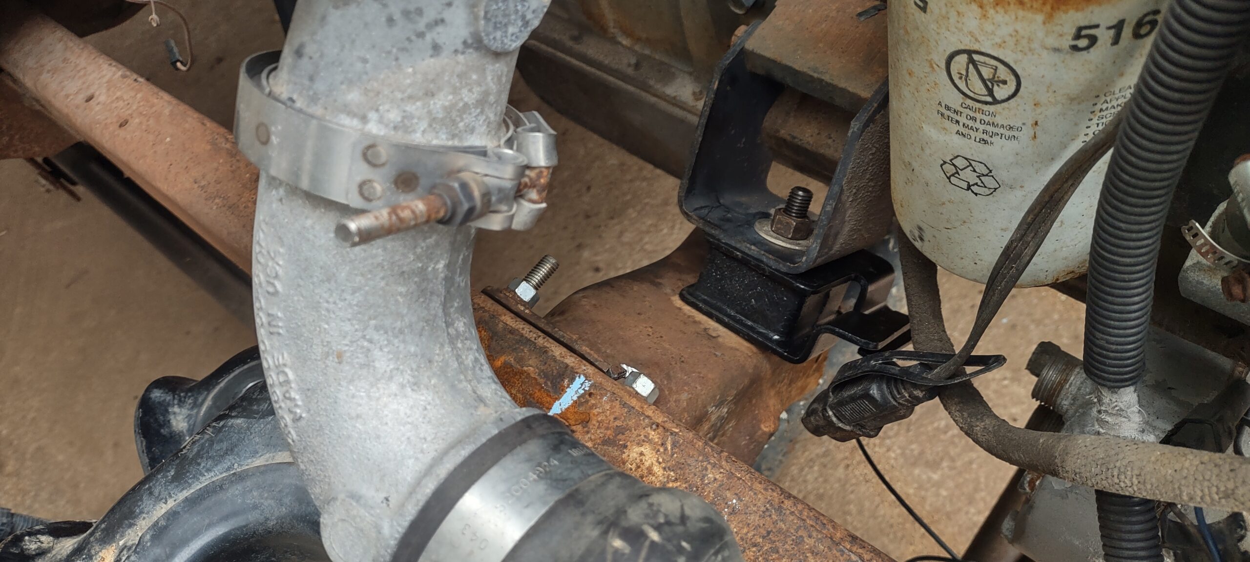
For the engine mounts: these mounts were harvested from a 1st Gen W-series Dodge. It needs to be W-series because it is the 4×4 version of the Dodge. The D-series is a 2×4 and the mount is more of a subframe assembly since there isn’t a front axle. This is usually a cross member that is riveted to the frame. It’s highly sought after for those converting their 2×4 to a 4×4, and they usually come at a premium. I got lucky and found a cut up cross member for free with some other parts, plus a 3 hour drive. The width of a 1st Gen is the same-ish-within-1/4″ as the Jeep. Mine is cut up so I only have the ends that attach to the motor and frame, and not the cradle part that goes under the engine. This is actually preferred for me because a lot of Dodge owners cut this out and make it bolt in because they can’t drop the oil pan with it there, if they ever needed to. I do plan on going back and making that modular piece as it will stiffen the frame in the front where all the weight is. I plan on doing this with C beam steel. Once the motor is roughly where it needs to be, with the engine mount pieces attached to motor, I will mark where they sit on the frame.
Here is another Tetris moment. I mounted the coil spring buckets (from a Super Duty F250) to the frame. The entire point of this was to keep it modular and easily replaceable, so I attached them with bolts. Originally they were also riveted on. These bolts go through the frame and protrude on the engine side. I will show this in my suspension post. I don’t know where the new aforementioned motor mounts will land on the frame but I have a suspicion it will be around where those protrusions are. I can choose to get longer bolts such they they attach both spring buckets and motor mounts, though, I don’t think I will be lucky enough to have that perfect of an alignment. It’s also not a great idea because if you ever want to replace a bucket, or a mount, you wind up unbolting bolting both which means the suspension comes out with the engine…? Not great. What this is leading to is I may wind up welding the buckets to the frame, or the mounts to the frame, or both. When I say mounts, I really mean the bracketry that is attached to the frame, where then the rubber isolator bolts to (which we recognize as the actual “motor mount”). Usually there isn’t a reason for that bracket to come out, you would unbolt the motor mount from the bracket to pull the motor, so maybe it is a better idea to weld the bracket on and keep the coil buckets modular. After all, the buckets can sometimes rust out.
That was a lot to say but it makes me feel more justified in my delay. This needs to be thought out for a successful install and future sustainment. This will make more sense once I make the other posts highlighting my suspension install, crossmember, and floor removal. The 240Z will be on hold until this milestone is complete. Parts taking up space need to be sold, scrapped, or installed, to clear the way for parts coming off from elsewhere.
In the meantime there is something I can be doing in the comfort of air condition. I need to draft wiring schematics. I am going to make a version of the stock platform (both vehicles), and then a modified version for my specific build. This will require the same thought process of planning and provisioning.
See you there.